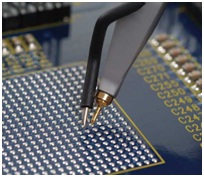
Figure 1: An example of an active oscilloscope probe
To speak of an oscilloscope probe is to open a fairly large can of worms. There are many kinds of probes on the market, with differing functions and characteristics (Figure 1). This is the first in a short series of posts on the basics on probes, what the various kinds are used for, and how they might be expected to affect measurements taken with them.
At the highest level, a “probe” can be anything that gets a signal from the device or circuit under test into the oscilloscope’s input channels. It can be anything from a short piece of wire to a high-bandwidth differential probe. A basic probe consists of some type of connector (BNC), a length of wire, and a probe head, the latter being the connection point of the probe to the circuit.
Next, let’s take a brief look at the four basic probe varieties:
Passive probe:
- Standard oscilloscope probe supplied by all scope manufacturers
- No active devices, only passive parts
- Physically and electrically robust – rugged mechanical design with the ability to measure several hundred volts
- Maximum bandwidth is 500 MHz but at the higher frequencies probe loading becomes an issue
Active Probe:
- Usually an optional probe that is powered by the oscilloscope through a connector on the front panel
- Based off of an active device such as a transistor or FET
- Not as robust as passive probe but much wider bandwidths and much lower capacitance
- The ideal probe for high frequency measurements
Differential Probe:
- Measures the difference between two signals when there is no ground reference
- Comes in two flavors:
- High voltage for floating measurements in a power supply, lighting ballast, motor drive, etc.
- High bandwidth for differential serial data streams
Current Probe:
- Active device that measures the current in a signal rather than the voltage
- Three main types:
- Transformer based; Hall effect devices; or combination transformer/Hall effect
- Most modern clamp on current probes are combination transformer/Hall effect
Now, understand that probes affect devices under test. Tradeoffs between different types of probes and how the electrical characteristics of the probe affect a circuit are important to understand to ensure accurate and reliable measurements.
A number of things can happen when a probe is connected to a circuit. In the best case, the true size and shape of the signal gets into the oscilloscope and is displayed on screen. Another possible outcome is that the probe alters the signal in some way and what gets displayed on screen is not what’s really happening at the probing point. A worst-case outcome is that the operation of the DUT changes; a well-designed device or circuit may malfunction (or vice-versa).
When a probe is connected to a circuit, it takes some of the energy present in the circuit and transfers it to the oscilloscope input. The probe constitutes another load that must be driven by the signal source. This load on the circuit can change the signal’s shape and change the behavior of the DUT.
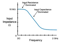
Figure 2: A plot of probe input impedance vs. frequency
Probes are designed with high resistance in the probe tip in the hope of reducing the energy drawn from the circuit and, thus, to reduce the loading. High input resistance is important but it only makes a difference at DC or at low-frequency AC. Let’s consider the effects of frequency on the probe’s impedance. At different frequencies, different characteristics of the probe gain importance (Figure 2):
- At DC or low frequencies, the high input resistance dominates the overall impedance
- As frequency increases, the capacitance dominates the impedance and dramatically lowers the overall impedance
- The result of the high probe capacitance shows up in the signal shape seen on screen
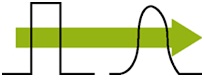
Figure 3: High probe capacitance can turn a pulse’s edges to mush
At 1 Hz, the impedance of a passive probe is 10 MΩ. At 1 MHz, that value decreases to 17.4 kΩ. At 100 MHz, impedance is just 174 Ω. With such a sharp dropoff in overall impedance, it’s not surprising that the probe can have such a dramatic impact on what’s seen on screen (Figure 3). That’s why it’s important to understand these effects and how they can influence measurements.
That’s it for this first installment on probe basics. In an upcoming installment, we’ll look at more probe basics, including why the different types of probes are more useful in some applications than others.
Alle blogs van Teledyne LeCroy vindt u hier, neem voor meer informatie contact op met AR Benelux.
 New 4-Channel 1000 X-Series Oscilloscope (prices start at less than € 900)