 Door: TOP-electronics
 Q&A - What is the false summing node technique
Q
What is the "false summing node" technique and how can you use it to protect a power op-amp?
A
In certain scenarios, such as when a power op-amp is in current limit mode, its output is saturated, or its output is not able to keep up with the inputs (slew rate limit), the op-amp’s operational mode is non-linear. Therefore the differential input voltage is no longer 0V and the transfer function no longer is:

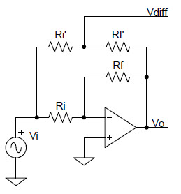
Detecting a nonzero input voltage can be used to sense that the op-amp is running in a non-linear mode and is in potential danger. But how can you "look" at the op-amp’s differential input voltage without disturbing its normal operation? This can be done by using the "false summing node" technique, which uses two extra series resistors between the circuit’s input and output:

VDIFF equals the power op-amp’s differential input voltage if:

This signal can be buffered and used to sense that the op-amp has entered non-linear mode and to prevent potential damage to the op-amp by shutting it down via further simple analog/digital circuitry, or via a microcontroller/DSP for more intelligent analysis.
Non-Linear Behavior Thermal Sleep Mode
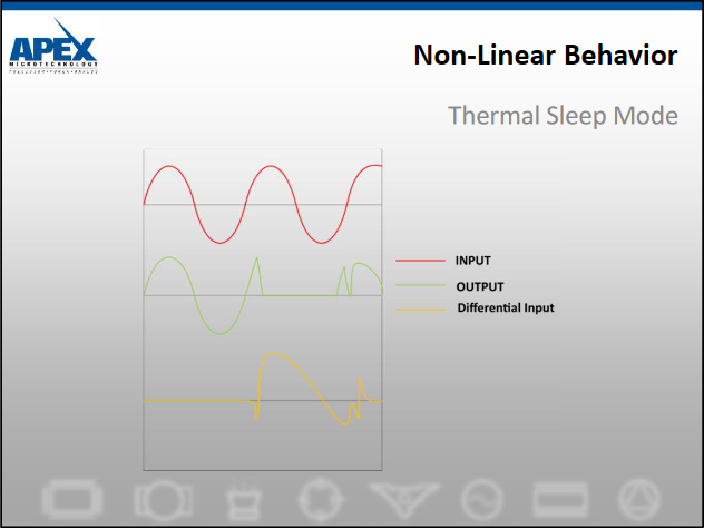
The situation with sleep mode is similar to thermal shutdown. In both cases, the amplifier is disabled by some circuitry which results in the output going into a high impedance state. One additional caution is that when coming out of sleep mode, an amplifier may saturate to one of the rails before recovering.
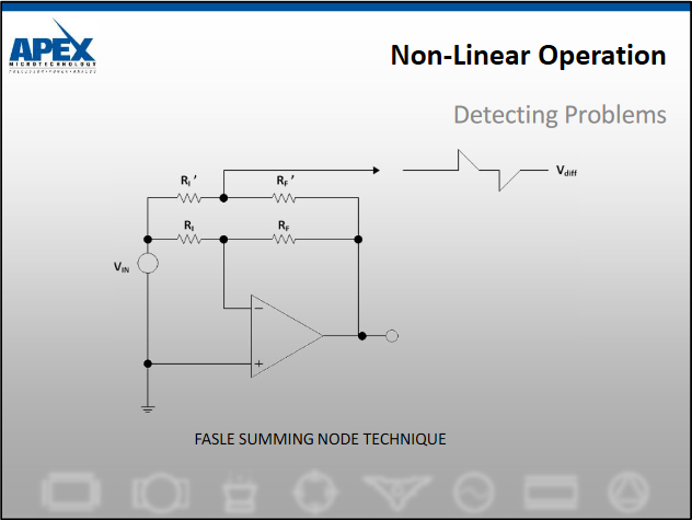
The common denominator of all non-linear modes of operation is the appearance of differential input voltages. One method of sensing when an amplifier is in a non-linear region is to use this false summing node technique.If Rf"/Ri'=Rf/Ri, then Vdiff equals the voltage at the inverting node of the amplifier. This buffered error voltage signal can be used as an error flag possibly to drive a logical latch that could shut down the system.
Would you like to know more? Contact the TOP-electronics team!