Introduction
For those familiar with measurements of ESD (electrostatic discharge) properties of infrastructures, the floor measurement probe should be a common item. But this probe can be used for more than just measuring the electrical conductivity of floors. Other uses include the measurement of electrical conductivity of work surfaces (tables, cabinet shelves, machinery etc.), but also chairs and solid planar materials (part of material science).

The construction and appearance of the probe has everything to do with what type of measurement is performed with it. As mentioned before: The probe is used to measure the electrical conductivity of an object. However, what is not said is that this conductivity is dependent on the applied test voltage and the applied pressure.

These parameters are important as they determine the outcome of the measurement. Even so much, that the contribution of the probe should be regarded as more critical, than the high impedance meter with which the measurement is performed. And yet, when a impedance measurement kit is offered for calibration, it is observed at many calibration companies, that they focus on the impedance meter and do not calibrate the probes.

Calibration of electrical (floor) resistance probes
The parameters of the floor probe are described in various standards: IEC 61340-4-1(US equivalent: ANSI STM7.1) , IEC61340-2-3 (US equivalent: ANSI STM4.1). Yes there are more standards that described these probes, but they basically come down to the same descriptive range.

  • The circular contact area (important when material resistivity is considered) is 65 mm +/- 5 mm in diameter
  • The weight (controlling the downward pressure parameter) is set to 2.5 kg +/- 10%, or 5 lb +/- 10%, should you follow US standards.
  • The hardness range of the conductive pad (controlling the surface contact capabilities) is set to 50 to 70 HA Shore A.
  • The conductivity (controlling the resistance contribution to the measurement circuit) may not exceed 1 kΩ (< 103 Ohm)

It must be noted that all parameters of the probe should apply to the finished product, not to individual parts of the probe. Should you offer floor resistance probes or any other ESD related resistance probe (like a 2-point probe or a concentric ring probe) for calibration, then these parameters should all be checked and reported upon in the calibration report.

Other aspects worth noting

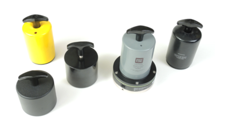
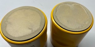
There are several floor resistance probe configurations available on the market. Some are fitted with carbon filled conductive pads, others with conductive pads containing silver particles. Both can do an equally good job, however, it has been observed that the ones (first generation) using a silver particle filled conductive pad, are more susceptible to wear/ degradation and react with solvents like isopropanol or ethanol. As a result, due to damage or degradation, these pads will become concave or convex (depending on where the wear/ degradation occurs). (See picture to the left)

Not all of this unintended “reshaping” of the conductive rubber pad surface can be observed with the naked eye. It can be measured though, using a device that measures the electrical conductivity over a set of predefined points across the pad area. The resulting resistance should lie in between a tightly fixed range. If this is not the case, then your probe is not flat and smooth anymore.

The effect of (unknowingly) using convex or concave conductive pads, is that less contact with the specimen occurs, which results in higher resistance values. This may lead to rejection of the floor, or any other materials under test using these probes.

Eurostatgroup – Pim Dik (co-auteur) | Total Esd Solutions – Tim Maas (co-auteur)

FHI, federatie van technologiebranches
en_GBEnglish (UK)